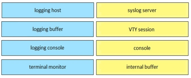
Drag and drop the logging configuration commands from the left on to the logging locations they configure on the right.
Select and Place:
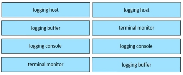
Answer is in the explanation below.
Reference / correct answer:
Question 2
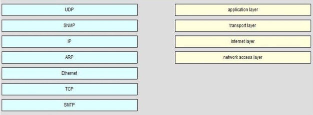
DRAG DROP
On the left are various network protocols. On the right are the layers of the TCP/IP model. Assuming a reliable connection is required, move the protocols on the left to the TCP/IP layers on the right to show the proper encapsulation for an email message sent by a host on a LAN. (Not all options are used.) Select and Place:
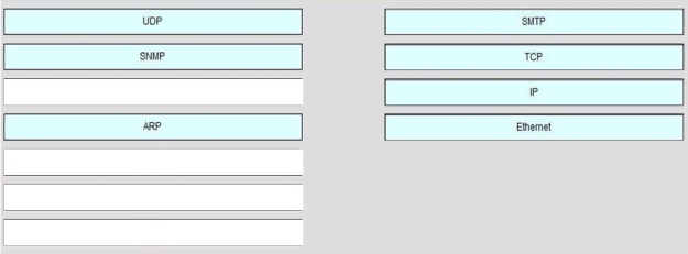
Answer is in the explanation below.
Reference / correct answer:
Question 3
SIMULATION
Instructions
Click the Instructions, Scenario, and Topology Tabs to toggle between the screens.
To minimize the windows, click the [-] button.
To reposition a window, you may drag it by the title bar.
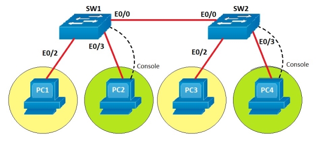
You are required to make appropriate configuration changes to SW1 and SW2.
To configure a switch, click the PC icons.
To access SW1 click PC2’s console and to access SW2 click PC4’s console. The console password configured for both switches is cisco (all lower case)
Note:
Most commands that use the “Control” or “Escape” key are not supported or necessary, and the help command does not display all commands of the help system.
Scenario
You work as a Junior Network Engineer for RADO Network Ltd Company. For testing purposes you are setting up a Layer 2 network in one of your client locations.
Topology Details
The two Switches, SW1 and SW2, are connected using an Ethernet link.
PC1 and PC2 are connected to SW1 and assigned to VLAN 700 and VLAN 800 respectively.
PC3 and PC4 are connected to SW2 and assigned to VLAN 700 and VLAN 800 respectively.
Configuration requirements
Create and name VLANs on both SW1 and SW2
VLAN 700 named as Sales
VLAN 800 named as Marketing
Note: VLAN names are case sensitive.
Configure the switch ports connected to the PCs as access ports.
Assign the switch ports to corresponding VLANs as indicated on the Topology Tab.
Manually configure the ports connected between SW1 and SW2 as trunk ports using IEEE 802.1q standards for trunk encapsulation.
Special Note: To gain the maximum number of points, you must complete the necessary configurations as per requirements.