DRAG DROP
You need to create the VM network for the development environment.
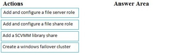
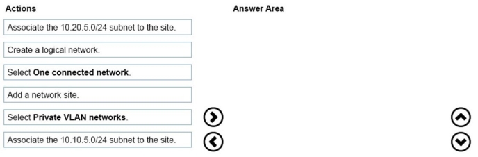
Which four actions should you perform in sequence? To answer, move the appropriate actions from the list of actions to the answer area and arrange them in the correct order.
Select and Place:
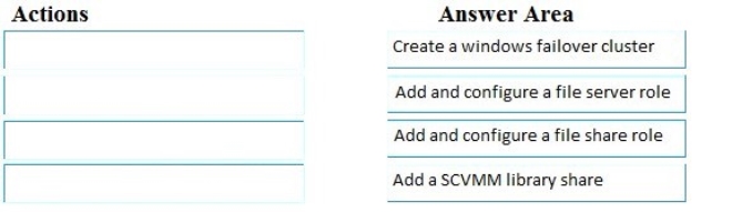
Answer is in the explanation below.
Reference / correct answer:
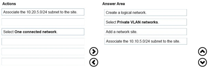
To create a logical network
1. Open the Fabric workspace.
2. On the Home tab, in the Show group, click Fabric Resources.
3. In the Fabric pane, expand Networking, and then click Logical Networks.
4. On the Home tab, in the Create group, click Create Logical Network.
The Create Logical Network Wizard opens.
5. On the Name page, do the following:
![]() Enter a name and optional description for the logical network.
Enter a name and optional description for the logical network.
For example, enter the name BACKEND, with the description Corporate network. Use for internal servers such as application and database servers.
![]() If you have System Center 2012 SP1 or System Center 2012 R2, select check boxes as appropriate by using the table that follows. Otherwise, skip to the next numbered step in this procedure.
If you have System Center 2012 SP1 or System Center 2012 R2, select check boxes as appropriate by using the table that follows. Otherwise, skip to the next numbered step in this procedure.
Select one or more check boxes based on how you intend to use the VM networks that will be configured on top of this logical network. The following table provides guidelines:
Use of the VM network or networks that will be created on top of this logical network
Action in System Center 2012 SP1
Action in System Center 2012 R2
Hyper-V network
virtualization: multiple VM networks with
isolation
Select Allow new VM networks created on this logical network to use network virtualization.
Select One connected network and then select Allow new VM networks created on this logical network to use network virtualization.
VLAN-based configuration: manage VLANs that have been created for network isolation within the physical network
Select Network sites within this logical network are not connected.
If you are using private VLAN technology, also select Network sites within this logical network contain
private VLANs. (Otherwise, do not
select it.)
For information about additional steps for this configuration, see “VLANbased configuration” in the list in Configuring VM Networks and Gateways in VMM.
In most cases, select VLAN-based independent networks. However, if you are using private VLAN technology, select Private VLAN (PVLAN) networks.
For information about additional steps for this configuration, see “VLAN-based configuration” in the list in Configuring VM Networks and Gateways in VMM.
One VM network that gives direct access to the logical network: no isolation
If this logical network will support network virtualization (in addition to having a VM network that gives direct access to the logical network), select the check box to allow network virtualization. If this logical network will not use network virtualization at all, leave all check boxes cleared.
Select One connected network and select Create a VM network with the same name to allow virtual machines to access this logical network directly. If this logical network will also support network virtualization, select the check box to allow network virtualization.
If you select One connected network but you do not create the VM network now, you will still be able to create the VM network later.
External networks: use VMM in coordination with a virtual switch extension, network manager, or vendor network-management console
Do not create the logical network manually from within VMM. Instead, follow the steps in How to Add a Virtual Switch Extension Manager in System Center 2012 SP1. The logical network settings will be imported from the database in the vendor networkmanagement console (also known as the management console for a forwarding extension).
Follow the steps in How to Add a Virtual
Switch Extension or Network Manager in System Center 2012 R2, and be sure to review the capabilities of your virtual switch extension or network manager. You might be able to configure your logical networks in VMM and then export the settings to the virtual switch extension or network manager. In any case, after you add a virtual switch extension or network manager, logical network settings configured in it will be imported into VMM.
6. Click Next.
7. On the Network Site page, take the following steps.
Note
For guidelines for configuring network sites, see “Network sites” in Configuring Logical Networking in VMM Overview. If you do not need to configure network sites, on the Network Site page, click Next, and then click Finish to complete the wizard.
1. To create a network site, click Add.
VMM automatically generates a site name that consists of the logical network name, followed by an underscore and a number.
2. Review the network site name and ensure that it is no longer than 64 characters. To change the default name, in the Network site name box, enter a new name for the network site.
For example, enter the name BACKEND - Seattle.
3. Under Host groups that can use this network site, select the check box next to each host group to which you want to make the logical network available.
For example, to make the BACKEND logical network available to the Seattle host group and all its child host groups, select the check box next to Seattle.
4. Under Associated VLANs and IP subnets, enter the VLANs and IP subnets that you want to assign to the network site. To enter VLAN and IP subnet information, click Insert row, click the field under VLAN or IP subnet, depending on what you want to configure, and then enter a VLAN, an IP subnet, or a subnet/VLAN pair. You can insert multiple rows. For example, add the IP subnet/VLAN pair that makes up the example BACKEND network in Seattle, as shown in the following table.
VLAN
IP subnet
7
10.0.0.0/24
Important
In your test environment, make sure that you use VLANs and IP subnets that are available in your network.
5. Optionally, create additional network sites by clicking Add and repeating the process.
6. When you complete this step, click Next.
8. On the Summary page, review the settings, and then click Finish.
The Jobs dialog box appears. Make sure the job has a status of Completed, and then close the dialog box.
9. Verify that the logical network appears in the Logical Networks and IP Pools pane. Also, if you added network sites, right-click the logical network, click Properties, click the Network Site tab, and verify that the intended network sites appear on the tab.
References: https://technet.microsoft.com/en-us/library/gg610588(v=sc.12).aspx